Guide Contents
✅ Pre-Installation Checklist
Before starting, use the following list to make sure you have all the tools for the job!
- Does the DV7 kit have all of the following?
- Power harness (DV772/DV775/DV778 as per the order placed)
- DV7 camera unit (DV703)
- Camera side cover (DV710)
- Long bracket (DV715) with VHB/Short bracket (DV714) with VHB as per the order placed
- T8/T20 security Torx wrench
-
- Alcohol wipes
- 3M® primer pen
- 2x 4" & 2x 8" cable ties
- Is the windshield glass temperature above 50º F?
- Do you have the appropriate Company Key?
- Installers and Partner users are required to enter this key before continuing with installations, however this step is not required for Fleet Manager users.
- The Company Key is also mentioned in the welcome email you received, when your RoscoLive account was created.
Installer App
Installation of Rosco products requires the use of the Rosco Installer App to ensure proper setup and configuration. If you do not already have the app installed, scan the QR code with your mobile device and select either iOS or Android to download the Rosco Installer App.
If you already have an existing account on RoscoLive, you can use these credentials to log into the app. Please note that only certain users can actually perform installations into your company - so if you do not see the "Install" option available to you, create a new set of credentials by tapping "Sign Up" on the login screen. Additionally, RoscoLive only allows 1 set of credentials to be associated with an email account so you can either use a different email to make the credentials OR create an "alias" email account by entering your email like the following:
[your normal email prefix]+installer@[your normal domain]
ex: If your normal email address is: john.doe@example.com - then your alias email will be: john.doe+installer@example.com

🛠️ Installation Steps
Once you have confirmed that all required tools and components are available, you are ready to begin the installation. You may follow the instructional video below or use the detailed step-by-step written instructions provided in the following sections.
Installation Video
Step 1. Mounting Location
a. Camera should be mounted as close to the center of the windshield as possible. If the windshield has a center divider, mount the camera as closely to the driver's side as possible without obstructing the view of the driver. (Fig. B)
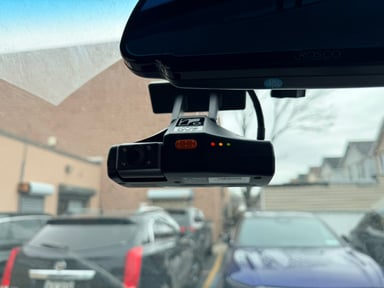
Fig. A
Step 2. Prep Windshield for Mounting
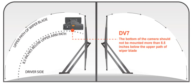
Fig. B
- Keep the camera lens within 8.5" below the tips of the windshield blades.
- The camera lens MUST be within the wiper pattern to ensure proper visibility.

Fig. C

Fig. D
It is important to let the primer properly cure for 5 minutes before mounting the camera. Failure to do so will result in an incomplete bond with the adhesive pad which will lead to the camera falling off the windshield during operation.
Windshield temperature needs to be at least above 50ºF (10ºC) for proper curing and adhesion. It is recommended to apply a heat gun to the mounting area or turn on the vehicle's defrost prior to applying primer to ensure proper glass temperature.
Step 3. Prep the Vehicle
a. Loosen the panels as needed to allow routing of the wiring. (Fig. E)
Fig. E
b. Remove the panels beneath the dashboard and around the steering wheel/column to access the OBD-II or J-BUS connections and the yellow ignition (IGN) wire. (Fig. F)

Step 4. Running Power Harness
The required harness depends on the type of installation being performed. The following section outlines the procedures for each harness type. Identify the harness you are using and follow the corresponding steps below.
Power harnesses are purchased separately from the base DV7 package.
1. DV778 Advanced Hardwiring vehicle connection (with Ch3/4 connection)

Fig. G
a. Locate the ignition (IGN) and power (BATT) wires, then use a pair of pliers to install the provided TTAP connectors onto the wires (Red: 22–18 AWG, Blue: 16–14 AWG, Yellow: 12 AWG). (Fig. H)

Fig. H
b. Connect the spade connectors of wires to TTAPs. (Fig. J)

Fig. J
c. For installation of the ground (GND) wire with the ring terminal, identify a suitable bare metal surface and secure the ground wire using the provided self-tapping screw. (Fig. K)

Fig. K
d. This harness includes two 4-port camera connectors that support up to two separate external camera connections or can be expanded to support up to four cameras per port using the STSS1200 multiplexer on each port. It also features an 8-pin Molex connector for integration with an external driver event harness, a sensor harness, or a ME (Mobileye) connection. Please refer to the end of this section for information on the adapter harnesses.
2. DV775 Advanced OBD-II vehicle connection (with Ch3/4 connection)
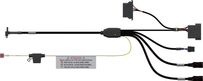
Fig. L
a. Locate and remove the vehicle’s female OBD-II connector from its mounting location.
b. Connect the DV775 OBD-II male connector to the vehicle’s female connector. (Fig. M).
c. Reinstall the DV775 OBD-II female connector in the vehicle’s original OBD-II mounting location. (Fig. N)
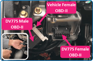
Fig. M (inset), Fig. N
d. Locate the ignition (IGN) wire and use a pair of pliers to install the provided TTAP connectors onto the wires (Red: 22–18 AWG, Blue: 16–14 AWG, Yellow: 12 AWG). Connect the spade connector of the Ignition wire to TTAPs. (Fig. H & Fig. J)
e. This harness includes two 4-port camera connectors that support up to two separate external camera connections or can be expanded to support up to four cameras per port using the STSS1200 multiplexer on each port. It also features an 8-pin Molex connector for integration with an external driver event harness, a sensor harness, or a ME (Mobileye) connection. Please refer to the end of this section for information on the adapter harnesses.
3. DV772 Advanced J1939 Vehicle Connection (with Ch3/4 connection)
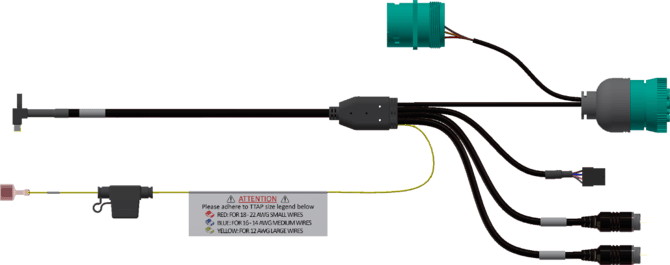
Fig. O
a. Locate and remove the vehicle’s male J1939 connector from its mounting location.
b. Connect the DV772 female J1939 connector to the vehicle’s male connector. (Fig. P)
c. Reinstall the DV772 male J1939 connector in the vehicle’s original J1939 mounting position. (Fig. Q)
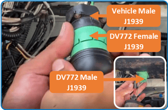
Fig. P, Fig. Q (inset)
d. Locate the ignition (IGN) wire and use a pair of pliers to install the provided TTAP connectors onto the wires (Red: 22–18 AWG, Blue: 16–14 AWG, Yellow: 12 AWG). Connect the spade connector of the Ignition wire to TTAPs. (Fig. H & Fig. J).
e. This harness includes two 4-port camera connectors that support up to two separate external camera connections or can be expanded to support up to four cameras per port using the STSS1200 multiplexer on each port. It also features an 8-pin Molex connector for integration with an external driver event harness, a sensor harness, or a ME (Mobileye) connection. Please refer to the end of this section for information on the adapter harnesses.
4. Adapter Harnesses
(8-Pin Y-cable for Sensor, External Driver Event Button & 2nd CAN supporting ME (Mobileye) Connection)

Fig: STSH491 Adapter Harness

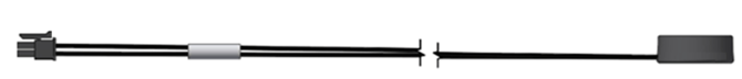
Fig: STSH492 External Driver Button Harness
![]()
Fig: STSH493 External Sensor Harness
Step 5. Rosco Installer App
If you have not already done so, open the Rosco Installer App on your mobile device and log in. Once logged in, tap the Install button to begin device creation and follow the on-screen steps to complete the installation.
Do not reassemble the vehicle until you have completed the step in the app that requires capturing installation images.
After the installation is completed in the app, an Install Report for this device is automatically generated. The report includes all entered information and captured images, which are stored with the device’s records.
FOOTNOTES
-
If you are completing the installation using a partner’s installer app, refer to that app’s documentation for specific instructions on installing a Rosco product.
Please note that this guide is a living document and is subject to change. As we continue to gather feedback from installers and fleet operators, refine our procedures, and introduce new hardware or software features, we will update these instructions to reflect the most accurate and effective installation practices. We recommend reviewing this guide online prior to each installation to ensure you are working from the most current version.